PCB Assembly
Gerber export
This mod’s PCB can be poroduced by many Chinese low-cost PCB manufacturers like JLCPCB or PCBWay using this Gerber file (ZIP).
Bill of Materials
| Designator | Value | Footprint | Description | Quantity |
|---|---|---|---|---|
| R12 | 1 M | 0805 | Resistor 250mW | 1 |
| R4 | 47.5 k | 0603 | Resistor 250mW | 1 |
| R3 | 22.1k | 0603 | Resistor 250mW | 1 |
| R11, R6, R7, R8 | 10 k | 0603 | Resistor 250mW | 4 |
| R5 | 1 k | 0603 | Resistor 250mW | 1 |
| R13, R14, R15, R16 | 4.7 k | 0603 | Resistor 250mW | 4 |
| C9 | 10 uF | 0603 | Capacitor | 1 |
| C2, C3, C6 | 10 uF | 0805 | Capacitor | 3 |
| C5 | 1 uF | 0805 | Capacitor | 1 |
| C1, C7, C10 | 100 nF | 0603 | Capacitor | 2 |
| C11, C12 | 220 pF | 0603 | Capacitor | 2 |
| C4 | 100nF | 0805 | Capacitor | 1 |
| FB1, FB2 | - | 0805 | Ferrite bead | 2 |
| Q1, Q2 | MMS8050 | SOT-23-3 | NPN transistor | 2 |
| J1 | FH12-24S-0.5SH-1MP | - | FPC connector, 24p, pitch 0.5mm | 1 |
| J2 | DM3AT-SF-PEJM5 | - | micro SD Card holder | 1 |
| J3, J4 | FH12-6S-0.5SH-1MP | - | FPC connector, 6p, pitch 0.5mm | 2 |
| J5, J6 | FH12-8S-0.5SH-1MP | - | FPC connector, 8p, pitch 0.5mm | 2 |
| U1 | AMS1117-3.3 | SOT-223-3 | LDO 3.3V 1A | 1 |
| U2 | CP2102N | QFN-28-1EP_5x5mm | USB-to-UART bridge | 1 |
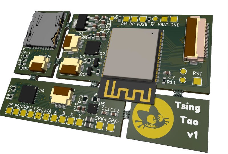
| U3 | ESP32-S3-WROOM-1 | - | ESP32 S3, Espressif | 1 |
| U4 | MCP23017_ML | QFN-28-1EP_6x6mm | I2C GPIO expander, 16 IO | 1 |
| U5 | MAX98357A | TQFN-16-1EP_3x3mm | I2S Audio DAC + Amp. | 1 |
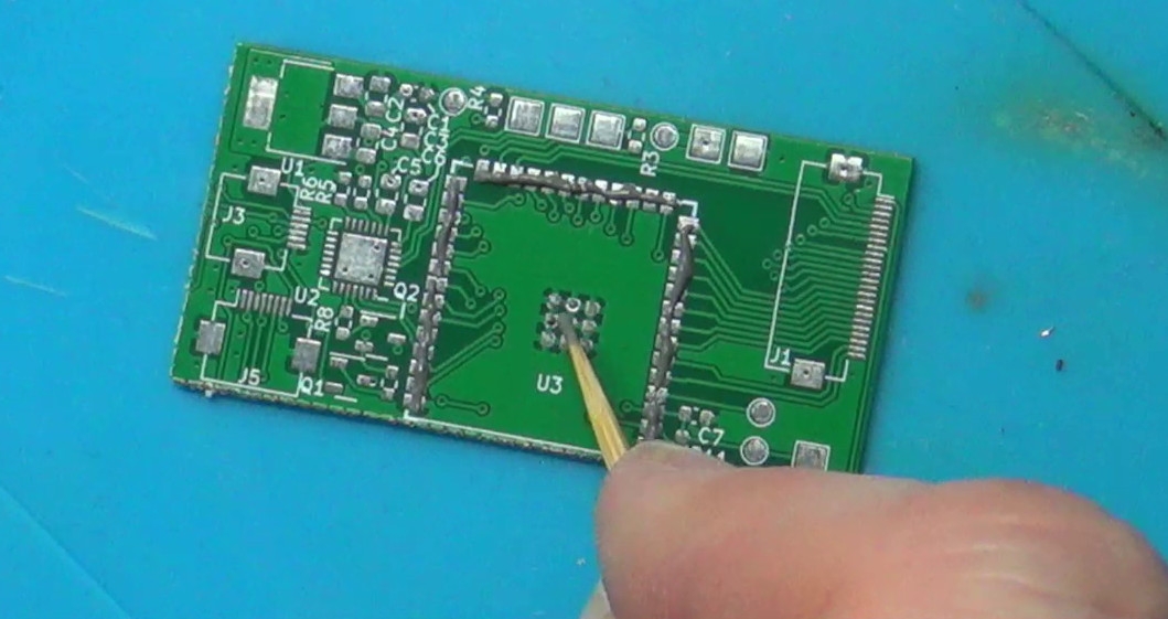
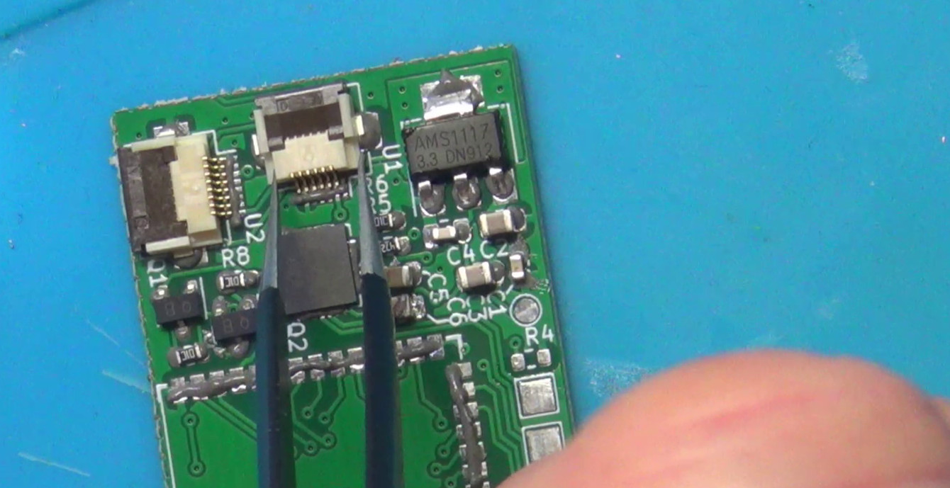
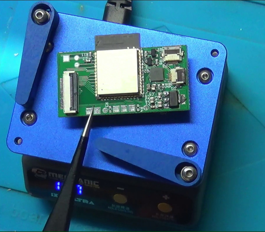
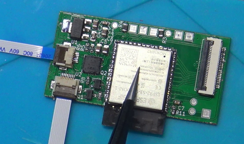
PCB soldering
Note: the pictures showed in this section have been taken during the soldering of the second prototype PCB. This previous version did not have mousebites and each section had to be soldered separately. The PCB version presented here does have mousebites and can be soldered in a single piece.
To solder this printed circuit board, use the classic procedure:
- apply solder paste using a stencil or by hand
- pick and place components manually (mind their orientation, especially for ICs)
- use a hot plate soldering device to heat up the PCB until the solder paste melt, make sure all components are soldered and remove from the hot plate.