Installation
This section details the installation of the TsingTao mod inside the console.
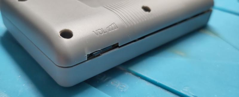
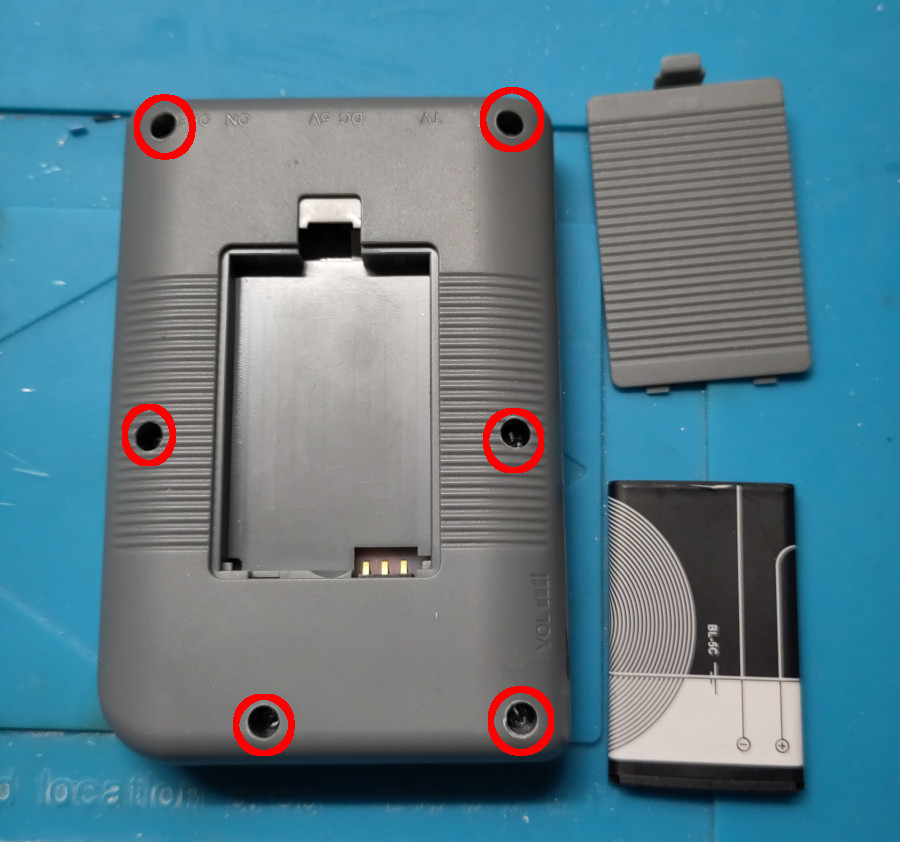
Disassembling the handeld
First, remove the console lid and battery located on the rear side of the device. Then remove the six screws holding the the two halves of the console’s main shell:
Once opened, extract the PCB from the device and put the two halves of the main shell aside. This PCB should look like the one below (note that there are a lot of variants for these handeld consoles, it is very likely that your PCB differs from the one showed here):
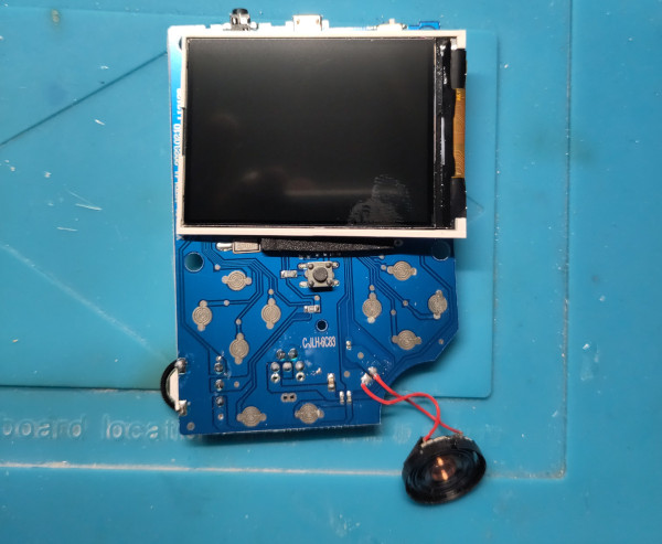
Disconnect the screen from the PCB: gently lift the socket’s lip with a plastic tool (avoid using a blade or a flat screwdriver as it may damage the screen’s ribbon) and caregully remove the ribbon from the socket. Keep this screen far from the workbench to avoid any scratch or damage (required in the final build).
Desolder the speaker using a soldering iron and a pair of tweezers. Keep it in a secure place to avoid any damage, we will need it later.
Prepping the board
We need to get rid of the original ASIC and flash memory to make some space for our mod:
- desolder the main Flash chip by using a soldering iron or a hot plate (flash chip aspect may differ from the one showed below, depending on the version and variant)
- with a dremel, cut the PCB following the lines showed below
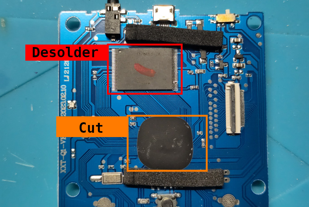
Please desolder and cut wisely, avoid touching any other critical components like those related to power supply, USB port or screen connector. Cut as close as possible from the ASIC (the big black epoxy blob) and try to keep the reset button intact (the tactile switch placed just below the ASIC).
Installing the main PCB
Once the ASIC and Flash chip removed, place the main PCB of the TsingTao mod onto the original PCB in a way the screen connector is placed close to its original location. Use some double-sided tape to stick it to the original PCB before doing any soldering job.
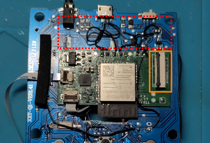
Avoid covering the area marked in red as it holds the power supply circuit and make sure the screen connector aligns perfectly with the original screen connector location (marked in orange).
Soldering the main mod’s PCB
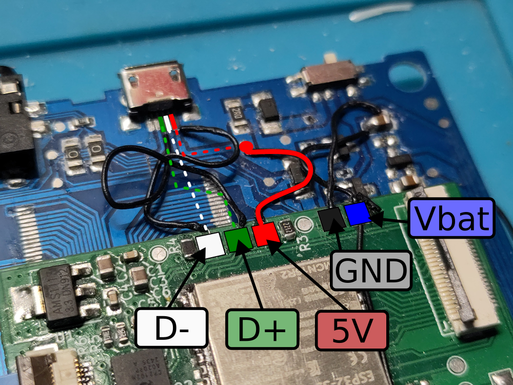
Before soldering, make sure you have already identified the main power supply lines:
+5Vprovided by the USB socketVbatthat corresponds to the battery voltage, usually wired to the device’s power switchGnd(basically tied to the original board’s ground plane and USB socket’s external case)
Cut the USB socket D+ and D- tracks and solder two wires:
- one from the socket’s
D+pad to the mod’s PCBDPpad - one from the socket’s
D-pad to the mod’s PCBDMpad
Then, solder the power supply wires:
- from the board’s
+5Vtaken from the USB socket to the mod’s PCB5Vpad - from the board’s
Vbatpower line to the mod’s PCBVBATpad - from the board’s
GNDto the mod’s PCBGNDpad
The mod’s main PCB is now conencted to the device’s USB port and power lines. We can test it by connecting it to a host computer through a USB cable while keeping its power switch set to OFF. A USB device should be shortly detected and then disconnected as the ESP32 is keeping rebooting (since it has not already been programmed).
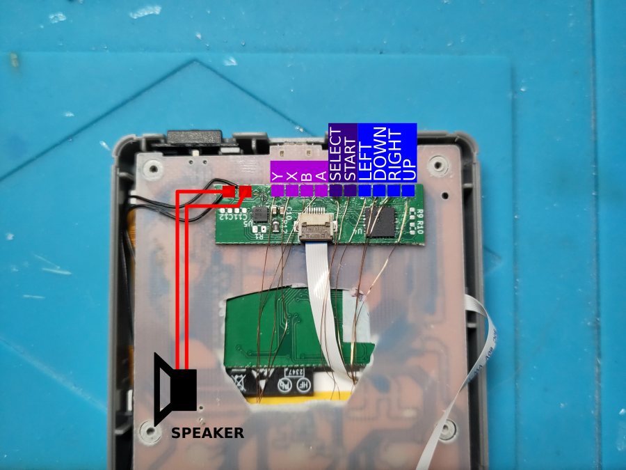
Soldering the auxiliary PCB (handling buttons and sound)
The mod’s auxiliary PCB is in charge of probing the console’s buttons and sending audio to the external speaker. It should be placed on the back side of the handeld’s original PCB, placed under the USB connector. This auxialiary PCB is connected to the mod’s main PCB through a 8-pin flat ribbon.
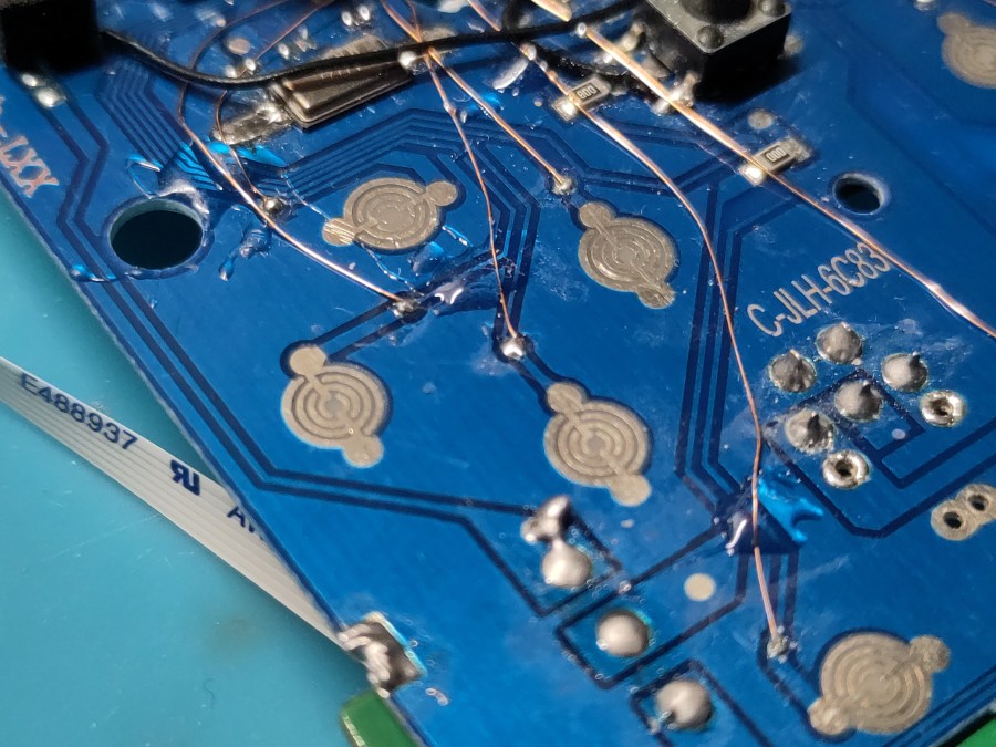
We use small enameled wires to connect the buttons to this PCB, as shown below:
Installing the SD card holder
Place and tape the SD card PCB module at the bottom of the original PCB’s back side, as showed below:
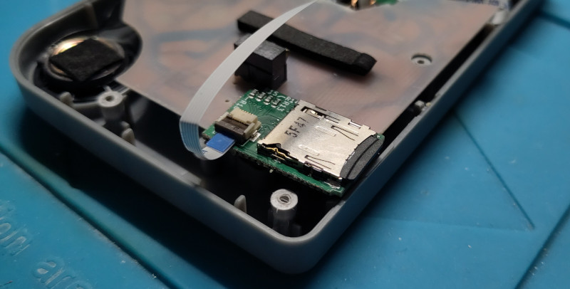
Once placed and secured, connect it to the main mod’s PCB using a 6-pin flex ribbon. Cut the main shell’s bottom half to make some room for the SD card and allow easy access from the outside. The picture below shows how it was done for our first prototype: