Teardown of the Cricut Maker Champagne
A low-cost CNC plotter
The Cricut Maker seems to be a low-cost CNC plotter/cutter using cheap parts (servo motors, gears) but relying on a strong metallic frame. Most of the plastic parts are injection-molded but somehow standards.
It does not use any ball bearing but some self-lubricating rings instead (for cost reduction).
Main PCB breakdown

The above PCB breakdown is from a Maker Champagne and contains the following components:
A PIC32 micro-controller (MCU)
A set of DC motor drivers (X/Y drivers, Head drivers)
A set of JST connectors to X/Y motors (X/Y motors and X/Y sensors)
A power stage with regulators and a barrel jack connector (Power)
A USB female connector used as the main communication channel with the host (Main USB interface)
A connector for the cutting/tracing head (Head conn.)
A bluetooth low energy module (Bluetooth module)
A connector for the top LEDs and buttons PCB (LEDs/buttons)
A debugging/programming connector (not populated, Debug/Prog)
PIC32 micro-controller
This main PCB uses a PIC32MX-family micro-controller, namely a PIC32MX470F512L. This is a 32-bit MCU with up to 512 KB of Flash memory and 128 KB of SRAM.
The datasheet is available here
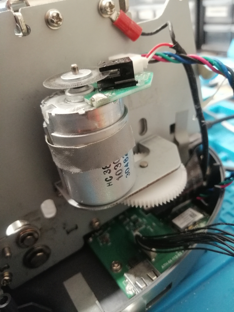
Servo motors
This Cricut Maker Champagne uses a set of servo motors using a quadrature encoder. The markings have been used to find out the exact model used.
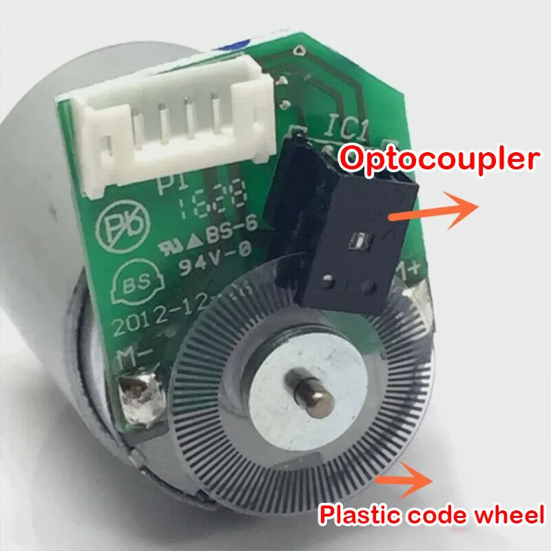
This is basically a DC motor coupled with a quadrature encoder, which is less precise than a stepper motor (like a NEMA17).
Bluetooth Low Energy module
The Cricut Maker relies on a Microchip RN4678 Bluetooth/Bluetooth LE module driven by a dedicated UART interface. This module interface has not been totally reversed yet.
The datasheet of this module is available here
Mechanical details
X axis is driven through a set of reduction gears coupled to a belt that drives the tool head.
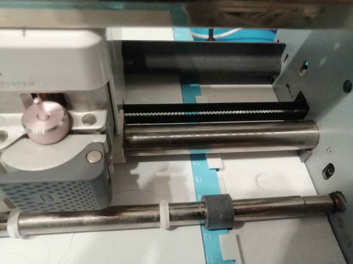
The machine Y axis however, is driven only by a set of reduction gears and drive rollers.
